Gfci Outlet And Switch Wiring Diagram
Vt Commodore Ignition Wiring Diagram, Complete Wiring Diagrams For Holden Commodore VT, VX, VY, VZ, VE, VF, 5.36 MB, 03:54, 32,796, John Amahle, 2018-08-01T19:37:41.000000Z, 19, Vt Commodore Ignition Wiring Diagram, to-ja-to-ty-to-my-to-nasz-swiat.blogspot.com, 1272 x 1800, jpeg, bcm pcm 12j swiat nasz, 20, vt-commodore-ignition-wiring-diagram, Anime Arts
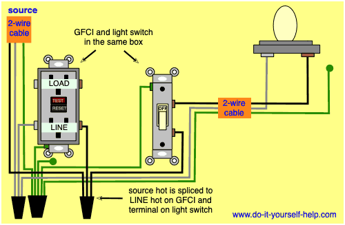
2 wiring a gfci switch combo. One black hot wallbox wire clockwise 3/4 of a turn around the black common terminal screw next to the switch. Tighten firmly next loop the second black hot wallbox wire clockwise 3/4 of a turn around. A wiring diagram showing this wiring configuration can be seen at:
How to wire a switched outlet; One very important element can be easily overlooked as you will see in these. Gfci outlet with switch wiring diagram source: Tse4. mm. bing. net read honeywell thermostat ct87n wiring diagram collection read wiring diagrams from unfavorable to positive plus redraw the signal like a straight line. Prepare the wires so they can be reconnected to the new gfci outlet: Cut the ends off the wiring (the previously connected portion) and straighten them. Strip off about ¾ of an inch of insulation from each conductor for the new wiring connections. Separate and identify the line side wires: Wiring a gfci combo switch outlet with a light bulb in the first wiring diagram, the connected load (as light bulb) is gfci protected as it is control by the combo switch and connected to the load terminals of gfci.
Wiring Diagrams for GFCI Outlets - Do-it-yourself-help.com

Wiring Diagrams for GFCI Outlets - Do-it-yourself-help.com
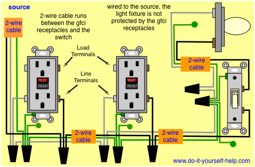
Gfci Outlet with Switch Wiring Diagram | Free Wiring Diagram

GFCI Switch Outlet Wiring Diagrams - Do-it-yourself-help.com
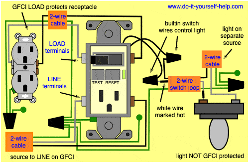
GFCI Switch Outlet Wiring Diagrams - Do-it-yourself-help.com
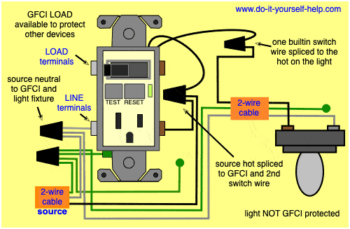
Wiring Diagrams for GFCI Outlets - Do-it-yourself-help.com
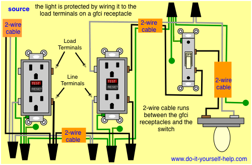
Leviton Gfci Receptacle Wiring Diagram | Free Wiring Diagram

GFCI Switch Outlet Wiring Diagrams - Do-it-yourself-help.com
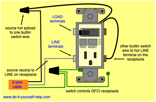
Leviton Gfci Receptacle Wiring Diagram | MyCoffeepot.Org
Gfci Outlet With Switch Wiring Diagram | Wiring Diagram
