Hampton Bay Wiring Diagram

Vt Commodore Ignition Wiring Diagram, Complete Wiring Diagrams For Holden Commodore VT, VX, VY, VZ, VE, VF, 5.36 MB, 03:54, 32,796, John Amahle, 2018-08-01T19:37:41.000000Z, 19, Vt Commodore Ignition Wiring Diagram, to-ja-to-ty-to-my-to-nasz-swiat.blogspot.com, 1272 x 1800, jpeg, bcm pcm 12j swiat nasz, 20, vt-commodore-ignition-wiring-diagram, Anime Arts
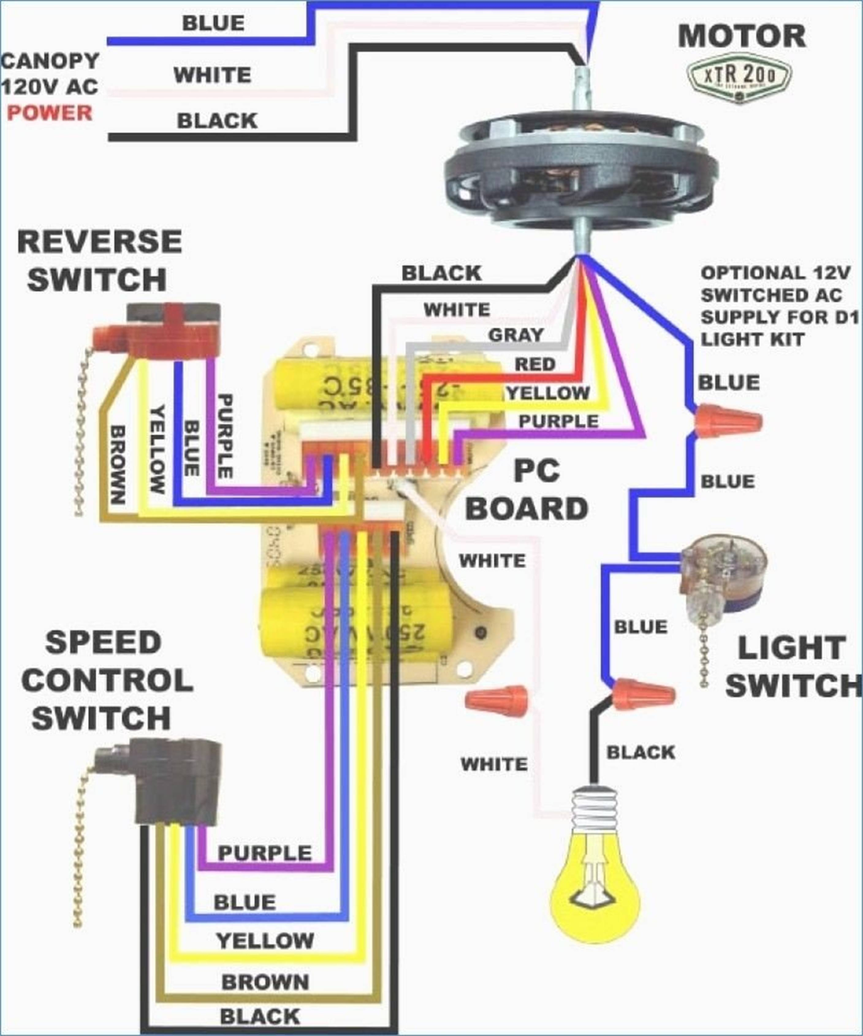
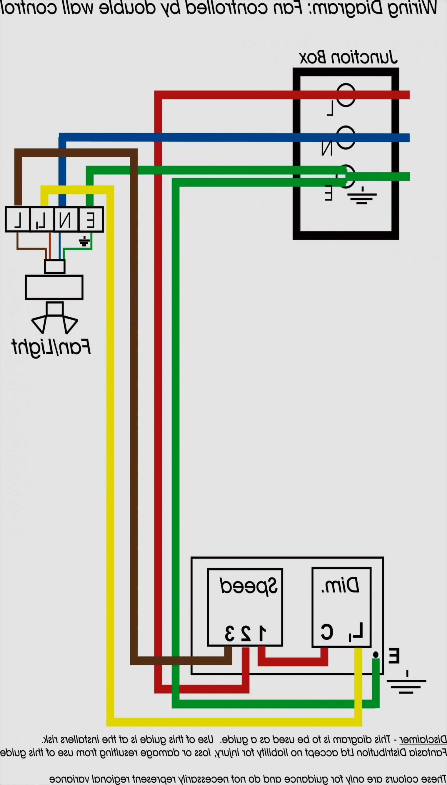
Hampton bay ceiling fan remote wiring diagram. repeat untill you have identified all the speed wires. Once that’s done, connect the wires the way you see below: Ceiling fan switch wiring diagram 2 line voltage enters the switch outlet box and the line wire connects to each switch. Hampton bay ceiling fan remote wiring.
How to wire a celling fan capacitor. Hampton bay ceiling fan replacement parts: How to find and replace them. Hampton bay customer service number. The hampton bay ceiling fan wiring diagram starts with the power source. The black wire is the hot wire and leads to the switch. The white wire is the neutral or common wire and goes straight to the outlet box. The green wire is. Hampton bay wiring diagram.
Hampton Bay Ceiling Fan Switch Wiring Diagram | Free Wiring Diagram

Hampton Bay 3 Speed Ceiling Fan Switch Wiring Diagram Download

Hampton Bay 3 Speed Ceiling Fan Switch Wiring Diagram - Wiring Diagram

Get Hampton Bay Ceiling Fan Capacitor Wiring Diagram Download

Hampton Bay Ceiling Fan Wiring Schematic | Free Wiring Diagram

Hampton Bay 3 Speed Ceiling Fan Switch Wiring Diagram - Wiring Diagram

Hampton Bay 3 Speed Ceiling Fan Switch Wiring Diagram - Cadician's Blog

Get Hampton Bay Ceiling Fan Capacitor Wiring Diagram Download

Checking your Hampton bay ceiling fan wiring to avoid misfortune | Warisan Lighting
Hampton Bay 3 Speed Ceiling Fan Switch Wiring Diagram Download
