Frc Wiring Diagram 2018

Vt Commodore Ignition Wiring Diagram, Complete Wiring Diagrams For Holden Commodore VT, VX, VY, VZ, VE, VF, 5.36 MB, 03:54, 32,796, John Amahle, 2018-08-01T19:37:41.000000Z, 19, Vt Commodore Ignition Wiring Diagram, to-ja-to-ty-to-my-to-nasz-swiat.blogspot.com, 1272 x 1800, jpeg, bcm pcm 12j swiat nasz, 20, vt-commodore-ignition-wiring-diagram, Anime Arts
There are several tools that are always essential to use in frc electronics, even though many teams aren’t familiar with them. These can make your life significantly easier throughout the process of building up the control systems on a robot. More information on electrical tooling can be found in the spectrum frc electrical guide. Measure and cut the wires to the right length with the motor wires.
Place the wire in the crimp and squeeze until fully crimped. Print the wiring diagram off plus use highlighters to be able to trace the circuit. When you use your finger or stick to the circuit along with your eyes, it’s easy to mistrace the circuit. A single trick that i actually 2 to print out the same wiring plan off twice. Upon one, i’ll trace the current movement, how it. Frc robot wiring diagram from docs. wpilib. org effectively read a cabling diagram, one provides to know how typically the components within the method operate. For instance , in case a module is usually powered up and it sends out the signal of half the voltage plus the technician would not know this, he would think he offers a challenge, as. It is the same manual that your local lexus dealer technicians use to diagnose and repair your lexus. The engine specific wiring diagram for infinitypro interface connections.
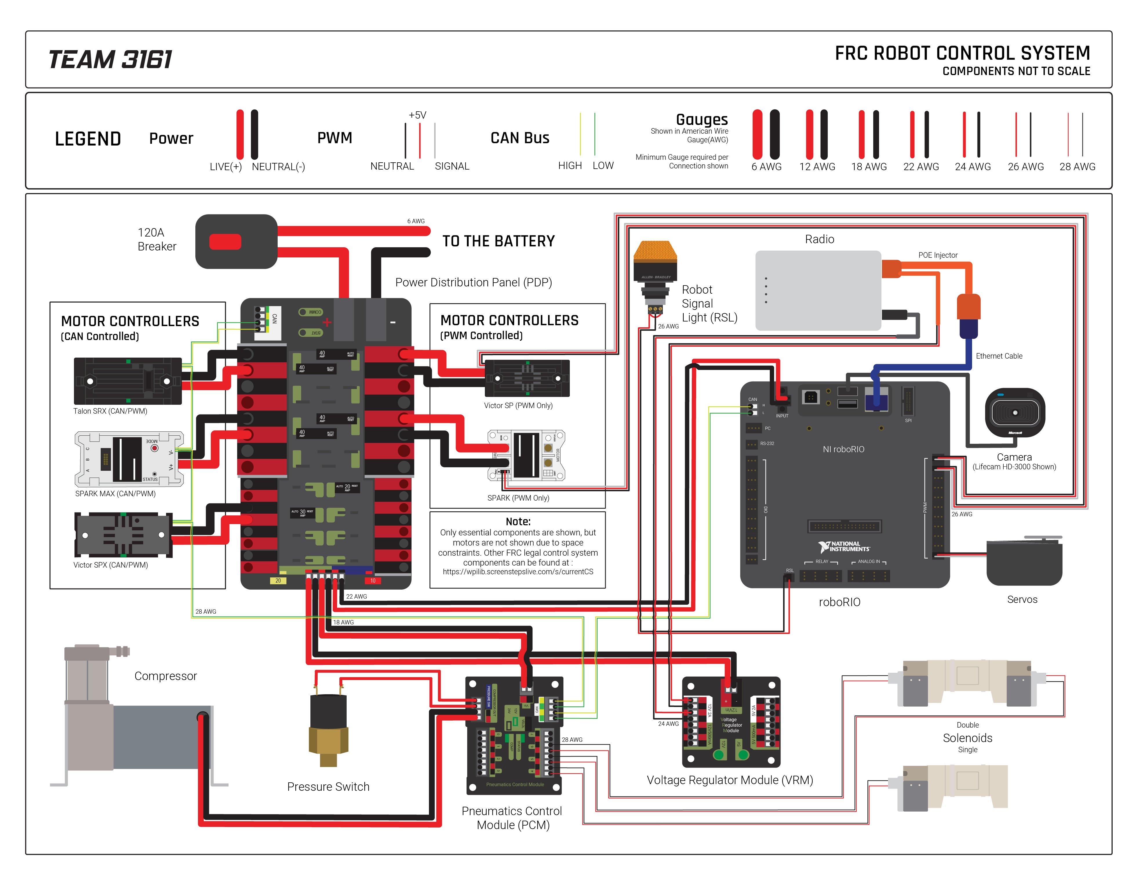
pic: Upgraded FRC Control System Wiring Diagram - CD-Media: Photos - Chief Delphi

Electrical Resources - NO GEARS, NO GLORY!
Wiring the FRC Control System | Getting Started with the Control System | 2018 FRC Control System

Creating Custom Parts for Robotics Competition - fritzing forum

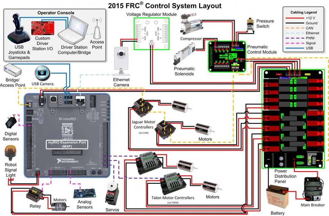
FRC Control System – Mr. McTavish
Frc Pneumatic Wiring Diagram | Wiring Diagram - Frc Wiring Diagram - Cadician's Blog

Bosch Seat Motor | Other KoP Item Resources | 2018 FRC Control System

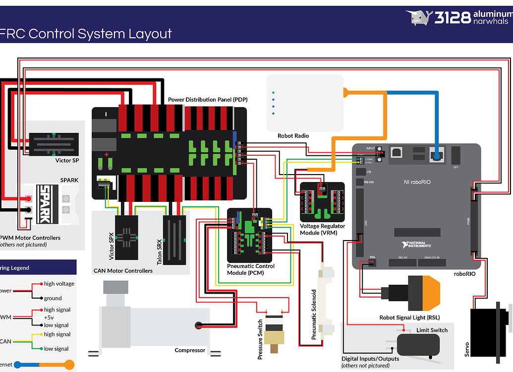
Control System Layout Infographic - Electrical - Chief Delphi

Unit 3: Computer Engineering Technology: Robotics and Control Systems
pic: Upgraded FRC Control System Wiring Diagram - CD-Media: Photos - Chief Delphi
